Assembly Simulation
with Virtual Reality
Project Overview
Abstract
Business process re-engineering is becoming a main focus in
today's efforts to overcome problems and deficits in the automotive and
aerospace industries (e.g., integration in international markets,
product complexity, increasing number of product variants, reduction in product
development time and cost).
With this project we apply virtual reality (VR) for virtual
prototyping (VP) to verify assembly and maintenance processes.
Partners
BMW AG, Munich, Germany.
Duration
summer 1996 - summer 1998
Movies
Functionality
This section presents some of the features present in the current
system.
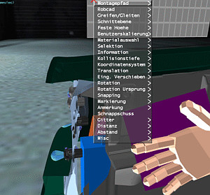 Multi-modal user interface
The user interacts with the VR system via several input channels: position tracking
(of his head, hand, etc.), gloves with gesture recognition (mainly used for grabbing),
voice input, and menues.
The system can use any type of display: monitor, stereo-projection, HMD,
and Cave.
In our experience, glove and HMD is best for this type of application.
Transformations
Functions in this section involve the motion of objects. The object's motion is
coupled directly to the user input, possibly with an additional constraint.
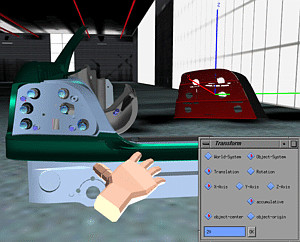 Transform
Objects can be transformed precisely by a simple 2D user-interface, by speech
input (the user says translate along x by ten). The user can choose between
the global car coordinate frame or the object's local coordinate frame.
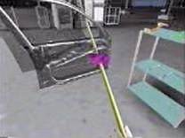
 Grabbing
Probably the most intuitive way to move objects is to simply grab them and put
them somewhere else.
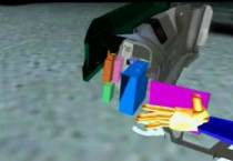
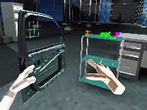
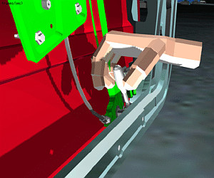
Collision prevention
In the "normal" grabbing mode, objects can penetrate other parts
(with highlighting of those).
Sometimes, one wants to move objects by grabbing them and still disallow
penetrations. The system provides for gliding of objects. In that
mode, objects being grabbed will not penetrate other parts; instead, they
will "glide" along the surface and try to follow the hand as much
as possible.
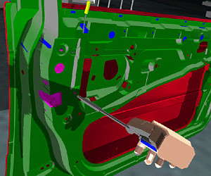
Restricted transformation
The motion of objects can be restricted when moved by the user's hand.
In this case, objects are not fixed rigidly to the user's hand; instead
they follow its motion, but only along one of the three coordinate axes
(local or global).
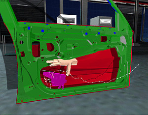 Assembly paths
During the motion of a part, its path can be recorded as an "assembly path".
Such paths can be played back, saved and loaded, edited, and many other functions
can be performed with them. They can be turned into a MPEG movie for later inclusion
in a HTML document. And they can be exported to other CAD systems.
Geometric Analyses
These are functions which help the user to analyze the geometric situation.
Typical actions involve collision detection, distance computations, etc.
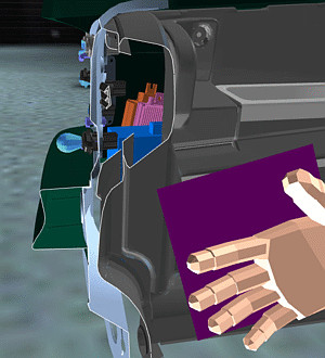
 Clipping plane
The user can examine the geometry more closely and more conveniently by a clipping
plane. When switched on, all geometry is clipped by that plane in real-time as
the user moves it through space. The motion of the plane can be resstricted like
other objects. The result of a clip operation can be highlighted and saved for
export to other CAD programs.
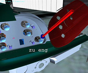
 Distance
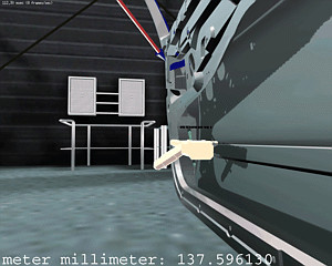
Distances between two parts can be measured interactively by two different metaphors:
the virtual yardstick and the rubber band. In both cases the VR system computes
the distance between two points on the surface of parts, and displays that as
2D text in a "heads-up" display.
Minimal distance
The VR system can compute the minimum distance between two parts.
When the computation is finished, the result is displayed in the heads-up
display.
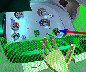 3D grids
In order to estimate the distance 3D and 2D grids can be displayed and positioned.
They come in a variety of pre-defined measures.
Penetration depth
When a part moves along its assembly path, it might penetrate other
objects. The maximum depth of any such penetration can be computed by the
system in near-real-time.
The result is displayed.
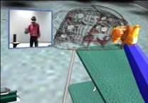
 Visualization of allowed rotation
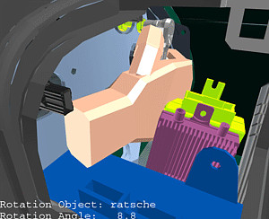
In order to find out the space a worker has to handle a wrench or other tool,
the system can display the collision-free amount of rotation.
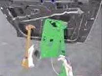
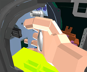
 Inverse kinematics
The system can compute simple inverse kinematics. This allows for "door-like"
mechanisms which can be manipulated by the user interactively. In addition, tools
can be made "snap" to snap on to screws and parts can snap into slots.
Whenever a tool or part is snapped in, it cannot be moved otherwise than
about the pre-defined axis of the screw/bolt/joint, resp.
Collision detection and handling
Several features exist to help the user find out collisions, clashes, or
near-clashes.
 Highlighting
When a part penetrates another one, it is highlighted red. When the get closer
to each other than the allowed safety distance, it will be highlighted in yellow.
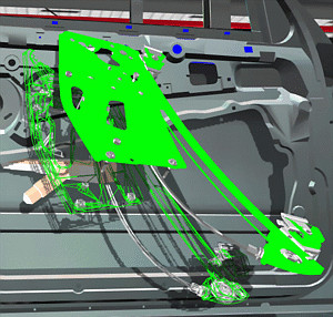
 Visualizing the collision area
Sometimes the user wants to see more details about the area of collision. In this
case, the system can display all polygons which are penetrating polygons of some
other part.
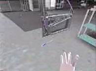
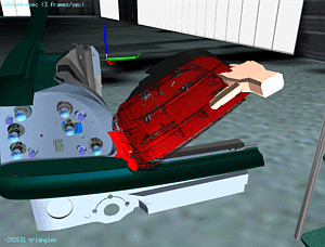
 The ghost
Another way of handling and displaying collisions is what we call the "ghost":
whenever a part penetrates another one, its solid representation will stay at
the last valid (i.e., collision-free) position. A wireframe representation (the
"ghost") will be placed by the system at the current actual position
of the colliding part.
Gliding
See Collision prevention
 Documentation
If a certain assembly task cannot be done, then the result of the verification
session should be a precise as well as intuitive understanding why that is.
During the VR session, the user can record certain results. At the end, the
system can compile a HTML page from the data.
Snapshot
Snapshots from the current viewpoint can be made.
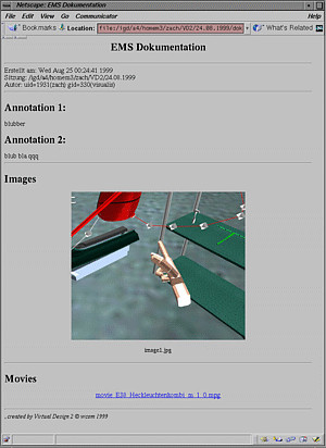
 Annotations
The user can place markers (e.g., arrows) in the scene and annotate these by spoken
text. The markers and texts can be saved for inclusion in the documentation.
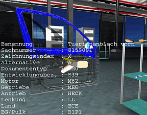 Part info
In order to verify that the currect versions of parts have been used to create
the virtual environment, the user can query all parts for their status information.
Modification of the (virtual) user representation
Functions in this section influence the way the VR system handles or
restricts some of the user's input.
Fixed height
The user can be fixed to a certain height. When navigating with
point-and-fly or spacemouse, this is practical when the user
wants to stay "on the ground", i.e., always keep the
"real" eye level.
User scale
Sometimes it can be convenient to scale the user to a different size than
what he shold really have compared to the virtual environment.
For instance, when the user wants to examine closely some details of the
geometry, his virtual representation can be scaled down.
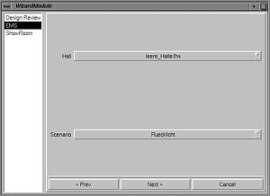
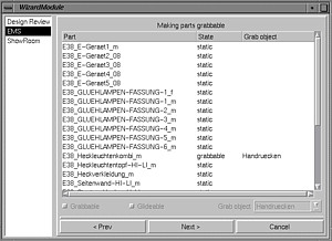
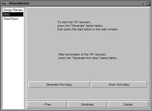
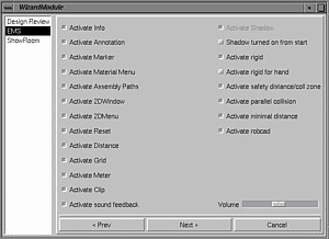
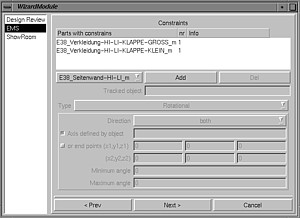
Creating a scenario
In order to create a new scenario for assembly simulation,
a high-level GUI (similar to Windows "wizards")
helps the user with configuration.
It asks the user to load the parts, tools, and other stuff,
then the user can configure certain behavior like, joints, physically-based
simulation, snapping, etc.
A lot of "standard" functionality does not need to be configured.
Other application areas, such as design review, and styling review,
have similar Wizards to help the user create scenarios in that application
domain.
More projects
Gabriel Zachmann
Last modified:
Sat Sep 10 16:01:26 MDT 2005